 |
                    
|
| Comparison V10 & V8 Engine |
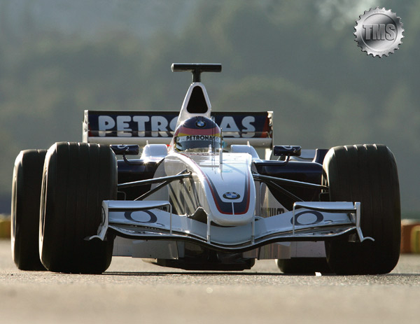
BMW Sauber F1 Engine 2006
Comparison V10 & V8 Engine
The decision to switch from V10 to V8 engines in Formula One was made at the end of 2004, leaving the engine specialists to focus their efforts over 2005 on the new regulations. 2006 sees the culmination of the switch-over phase.
As BMW Motorsport Director Mario Theissen explains: "The development of a V8 powerplant for Formula One represented a huge challenge for our engineers – especially given the relatively short amount of time at their disposal. The V8 is a totally different concept to the V10. The drop in output is roughly proportional to the 20 percent reduction in displacement. I would therefore expect lap times to climb by an average of one to two seconds. The reduced output on tap for the drivers means the cars will spend significantly more time per lap under peak loads. Reliability is top priority. We can't wait for the serious action to get under way in Bahrain on 12th March. Only then will we get an impression of who's really been doing their homework."
Differences
Although the V8 with the now compulsory cylinder angle of 90 degrees may look like a sawn-off V10, technically it is an entirely separate concept with its own specific requirements. The V8 has a distinct firing sequence and demands a fundamentally different crankshaft design. Whereas a 72-degree offset crankshaft was used in BMW's V10 Formula One engine, V8 powerplants can feature crankshafts with either four throws spaced at 90 degrees or four throws spaced at 180 degrees. Standard production engines are fitted with 90-degree crankshaft variants due to their better dynamic attributes, but a 180-degree crankshaft is favoured in racing car engine design. The improved performance this allows offsets the disadvantages in terms of dynamics.
Indeed, mechanical dynamics and vibrations represent a particularly critical area of development for the new generation of Formula One engines. The V8 units have different firing sequences and intervals from their V10 predecessors, which leads to a totally different situation in terms of vibrations. The V10 entered a critical area in terms of vibrations between 12,000 rpm and 14,000 rpm. However, this was not an issue as the engine did not spend much time in this rev band and smoothed itself out again once the driver stepped up the revs. And, since that was where it spent the majority of its time, vibrations were not a worry. A V8, on the other hand, is not so well off. Its vibration curve enters critical territory later than the V10 – from approximately 16,000 rpm – and continues to climb from there. It is therefore no longer possible to think in terms of getting through a difficult patch and everything will be all right. Now, the problem of constantly increasing vibrations has to be confronted head on. If you don't get a handle on vibrations, they will eat into the service life of the engine and multiply the loads exerted on chassis components. In order to get on top of this problem, the calculation and analysis of each individual engine component has to be totally reliable. However, analysis of the individual components is only part of a bigger challenge. Determining how they work with and against each other in simulations of the overall system is the main task.
Restrictions
Reduced mass should mean less in the way of "bad vibrations". However, the regulations have sensibly nipped any natural tendency among the teams to reach straight for exotic – and expensive – ultra-light materials in the bud. The engineers work with conventional titanium and aluminium alloys, as stipulated in the regulations. The new V8 has to be heavier than its predecessor, even though the 2005 engine had two extra cylinders. This season's powerplants must tip the scales at no less than 95 kilograms. This should include the intake system up to and including the air filter, fuel rail and injectors, ignition coils, sensors and wiring, alternator, coolant pumps and oil pumps. It does not include liquids, exhaust manifolds, heat protection shields, oil tanks, accumulators, heat exchangers and the hydraulic pump.
Added to which, the new regulations stipulate that the engine's centre of gravity must be at least 165 millimetres above the lower edge of the oil sump. The experts had previously managed to lower the ten-cylinder engine's centre of gravity to the benefit of the car’s handling. However, the longitudinal and lateral position of the V8's centre of gravity has to be in the geometric centre of the engine (+/-50 millimetres). For the technical commission, checking that everything is in order no longer consists of a simple weighing process. Now, making sure that the rules have been observed involves weighing on two levels and making calculations according to the lever principle.
Previously a closely guarded secret, the dimensions of the cylinder bore are now limited to a maximum 98 millimetres. The gap between the cylinders is also set out in the rulebook – at 106.5 millimetres (+/- 0.2 mm). The central axis of the crankshaft must not lie any less than 58 millimetres above the reference plane
Another critical change in the regulations is the ban on variable intake systems. Known as "trumpets", these systems could previously be used to optimise the car’s torque curve. The fixed duct lengths will now make achieving good engine driveability a more exacting challenge. The teams will have to strike a compromise between maximum power and good driveability. Where the best compromise for the pipe lengths is to be found depends on various factors. The track layout and the weather, for example, both play a role. The teams will favour one set of intake pipe lengths for circuits with long straights – like Monza, Indianapolis and Spa – where power is critical, and a different selection for twistier grand prix tracks such as Budapest and Monaco, where driveability relegates raw power to the back seat. The same applies in wet weather. The air intakes are, by definition, part of the engine and are included in its 95-kilogram maximum overall weight, but they can also be changed up to qualifying.
Joining variable intake systems on the black list are variable exhaust systems and variable valve control systems. The power supply to the engine electrics and electronics is limited to a maximum 17 volts and the fuel pump now has to be mechanically operated. Only an actuator may now be used to activate the throttle valve system. With the exception of the electric auxiliary pumps in the petrol tank, all sub-components must now be driven mechanically and directly via the engine.
Timeline
November 2004: Work begins on the design of the BMW P86.
May 2005: The first specification completes its test rig trial.
13 July 2005: A further specification is tested in practice for the first time.
Antonio Pizzonia pilots a Williams chassis specially adapted to accommodate the engine in Jerez.
28 November 2005: Another further development of the engine is fitted in an interim Sauber chassis for the start of winter testing in Barcelona.
17 January 2006: The next stage of development is fitted in the rear of the BMW Sauber F1.06 for the roll-out in Valencia.
17 February 2006: The first race specification of the P86 is given the green light.
Comparison
BMW P84/5 V10 (2005)
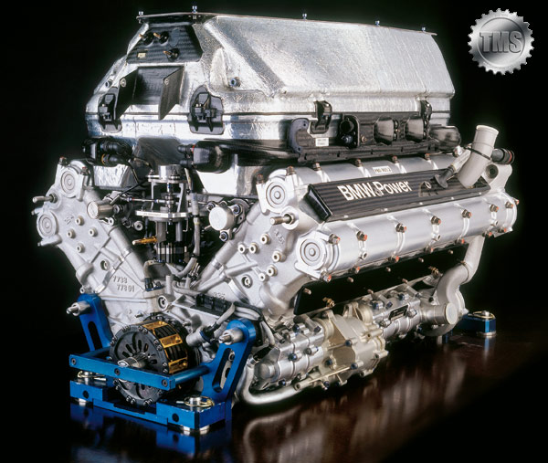
Cylinders: 10
Bank angle: 90 degrees
Displacement: 2,998 cc
Weight: 92 kg
Height: 320 mm
Width: 535 mm
Length: 578.5 mm
Output: 925 bhp
Engine speed: 19,000 rpm
Fuel consumption: 80 l /100 km
Total no. of parts: 5,200
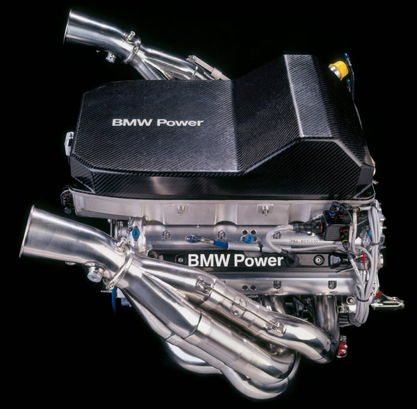
BMW P86 V8 (2006)
Cylinders: 8
Bank angle: 90 degrees
Displacement: 2,398 cc
Weight: 95 kg
Height: 325 mm
Width: 555 mm
Length: 518 mm
Output: over 720 bhp
Engine speed: 19,000 rpm
Fuel consumption: 65 l / 100 km
Total no. of parts: 5,000
The Story In Numbers
It takes 3 men 3 days to put together an engine
200 engines are used for trials, tests and grands prix
8 million ignitions per race
1,500 CAD drawings before the engine’s GP debut
Maximum piston acceleration: 10,000 g
Maximum piston speed: 40 metres per second
Average piston speed: 26 metres per second
A piston accelerates from 0 to 100 km/h in 0.3 thousandths of a second
3 tonnes of force is exerted on the connecting rod
Maximum temperature at exhaust: 950 degrees
Maximum air temperature in pneumatic system: 250 degrees
|
Copyright ©2000-©2023 TotalMotorSport
|